Pipelines are widely distributed and highly networked, meaning they are often influenced by interference voltages. This interference can come from many sources, such as electrified rail systems, high voltage lines, earth faults and lightning effects.
An interference voltage is defined as a voltage level that exceeds the system voltage and can present as a rapid transient, or as a temporary or prolonged overvoltage.
Pipelines are often coated to guard against corrosion, and systems such as cathodic protection is utilised to assist in the protection of the coated pipe sections. The cathodic protection system must also be protected from the effects of lightning related effects.
A pipeline can be threatened, irrespective of it being insulated, through a galvanic, inductive, or capacitive coupling of an interference voltage. This can be a frequent occurrence, and the consequences can be damage to installations, parts of installations, and to people.
Conductive pipelines are constructed with insulating joints (flanges) to provide electrical isolation of sections of pipe, to prevent corrosion caused by stray electrical currents. The interference voltages, particularly those related to the effects of lightning, will almost always exceed the dielectric strength of the insulating joint. This can result in open sparking or the destruction of the insulating material of the joint. Repairs to damage of this nature can be extremely expensive, inconvenient, potentially hazardous, and require significant downtime, particularly for long distance transmission pipelines.
To protect insulating joints from destruction caused by lightning related voltages and currents, an isolating spark gap should be used. An isolating spark gaps is often used for lightning equipotential bonding in many systems. If the environment is potentially explosive, the spark gap must be rated as explosion proof in accordance with the Ex-zone.
The selection of an isolating spark gap for an insulating joint must be in accordance with the electrical properties of the insulating clearance of the insulating joint. The spark gap is connected in parallel with the insulating joint, so careful coordination of the electrical properties is essential to ensure the electric equalizing process after a lightning discharge is performed by the spark gap, and not by the insulating clearance of the insulating coupling or flange of the pipeline.
A spark gap is a voltage switching device, so the switching value of the spark gap must occur below the dielectric strength of the insulation of the insulating joint. The insulation strength of these joints can be verified by applying an AC test voltage (Upw). Two classes are commonly used:
When testing the voltage levels of the joints, no puncture or flashover is allowed at the insulating joint.
To ensure compliance with the class levels of the insulating joint, the sparkover behaviour of the isolating spark gap is tested with a standardized lightning impulse voltage with a 1.2/50 µs wave form. The 100% lightning impulse sparkover voltage of the isolating spark gap must be less than half the insulation strength of the insulating joint (UPW). The requirements for isolating spark gaps is therefore:
For Class1: UPW= 2.5 kVrms(1.2/50 µs)
For Class2: UPW = 1.25 kVrms (1.2/50 µs)
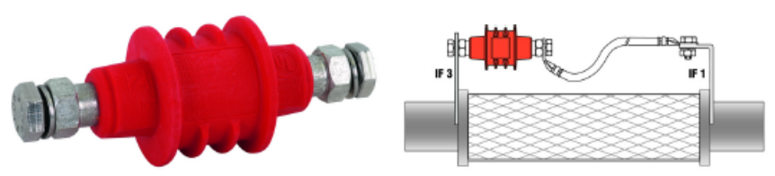 EXFS 100 isolating spark gap and installation example
The Dehn EXFS 100 isolating spark gap fulfills the requirements of a rated impulse sparkover voltage and is commonly utilized on pipelines across Australia.
IPD is the exclusive distributor of Dehn products in Australia and provides support for Australian customers on applications and training on lightning and surge protection requirements.